Carpinteri & Spagnoli method v.CMBS
The form of damage parameter designed by Carpinteri & Spagnoli ([CS01], [Spa01]) looks like this:
![]() ,
,
with material parameters given as:
![]()
NOTIFICATION: Papuga in [Ppg05] tested behavior of this damage parameter. He found that the inclusion of the mean stress effect is too strong. The implementation in PragTic thus uses the following form of the method:
![]() ,
,
with the mean stress effect alike to Smith, Watson & Topper (SWT) The original form using the quadrate of maximum normal stress gives poor results for higher values of mean stress, thus it is not implemented at all.
There are two distinct versions of Carpinteri & Spagnoli method implemented in PragTic. Both use the same SWT modification. In contrast to the original method described here, the other variant uses MD concept.
The method uses the CPD concept of critical plane definition. The method is based on a definition of weighted mean principal stress concept, first introduced in [CBM99] and [CMB99]. Note that the focus of the report is aimed at random loading. The concept utilizes three Euler angles between a global coordinate system and three principal directions 1, 2, 3 at any time instant as an appropriate parameter for averaging throughout the cycle. The report [CMB99] describes derivation of the three Euler angles from the 1, 2 and 3 principal directions. The procedure is implemented into PragTic in this way.
WARNING: The user should be warned, that this method fails to work under some circumstances. The problem is hidden in the algorithm given in the [CMB99], where some specific points of solution are not defined for some limit states. The problem is clearly announced and the calculation stops incorrectly, thus the user knows about it. I have not found any better solution until now.
Once the angles are derived, they are averaged with specific weights:
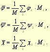
The subscript k corresponds to the k-th time instant, at which the angles were derivated. The Mk parameter is the weight given to the current k-th load state, whereas M is the sum of all weights throughout the one cycle:
![]()
Carpinteri et al. propose two different weight systems. As first, the common arithmetic average can be reached by setting Mk = 1. The second proposal is much more complicated:
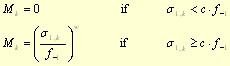
Here the c parameter is given to be lying somewhere in the range 0 < c < 1. The authors invariantly set it to a value of 0.5 without any explanation. This value is used in PragTic as well and cannot be modified by the user. Exponent w is the exponent of the S-N curve. The exponent w allows observing the S-N curve by such a weight and accentuate more the most damaging planes.
NOTIFICATION: Because w exponent cannot be accessible for some materials, Papuga in [Ppg05] tested also variants, where the exponent was invariantly set to 0 (i.e. this is the first proposal of C&S with Mk = 1) and 1 (i.e. the first principal stress was the weight). The comparison was limited to some 86 experimental points. The results of the comparison were very alike and no clear reason to prefer any of the three variants of the weight system was found.
Spagnoli [Spa01] and Carpinteri & Spagnoli [CS01] generalized the use of the described concept to the localization of the critical plane as well. They define that the critical plane should be deviated by an angle:
![]()
from the weighted mean first principal direction. The search angle is built in such a way that the critical plane is coincident with the plane of which the weighted mean first principal direction is the normal for brittle materials (fatigue limit ratio close to one), whereas for ductile steels with fatigue limit ration close to square root of 3 is the deviation angle 45°. A search procedure over all possible planes obeying such deviation angle is run. This is the point where the parameter Number of scanned planes in Calculation Methods menu is necessary. It defines number of planes, on which the search is performed, i.e. the 180 planes correspond to the 2° angular step.
Nomenclature:
|
Mark |
Unit |
PragTic variable |
Meaning |
|
|
[MPa] |
shear stress amplitude on an examined plane |
|
|
|
[MPa] |
TENS-1, BEND-1 |
fatigue limit in fully reversed axial loading |
|
|
[-] |
ratio of fatigue limits ( |
|
|
|
[MPa] |
amplitude of normal stress on the plane examined |
|
|
|
mean (average value of maximum and minimum values) normal stress on the plane examined |
||
|
|
[MPa] |
TORS-1 |
fatigue limit in fully reversed torsion |
|
|
[-] |
WF-1 |
exponent of S-N curve for fully reversed tension-compression |
|
|
[rad] |
Euler angles of the plane examined |
Methods & Options & Variables of Calculation – Edit
Decomposition
Elasto-plasticity
- No – currently no option implemented
Solution option
- Number of scanned planes
- Only every x-th data-point taken from load history
- Optimize <1~yes, 0~no>
- Evaluate envelope curve only <1~yes, 0~no>
Solution variable
- Minimum damage – this option is not active for this high-cycle fatigue method
Material parameters
|
E |
[MPa] |
tensile modulus |
|
NU |
[-] |
Poisson’s ratio |
|
TENS-1 |
[MPa] |
fatigue limit in fully reversed push-pull (or plane bending) |
|
TORS-1 |
[MPa] |
fatigue limit in fully reversed torsion |
|
WF-1 |
[-] |
exponent of S-N curve for fully reversed tension-compression |
Result detail variables
Damage fatigue index is computed, not the damage as a reciprocal value to number of cycles or repetitions
FDD1 NCX x-coordinate of the normal line vector of the critical plane
FDD2 NCY y-coordinate of the normal line vector of the critical plane
FDD3 NCZ z-coordinate of the normal line vector of the critical plane
FDD4 ALFA angle between the normal lines to the critical plane and to the free surface
© PragTic, 2007
This help file has been generated by the freeware version of HelpNDoc